


Spot Welder
Spring, 2017
So while making the storage bin shelving units I decided I didn't like how my solder joints on the boxes were turning out so I decided to get set up for spot welding. This is all part of expanding a sheet metal capability that I have been meaning to aquire for some time.
Anyway, at this point in time I don't have either the cash to purchase or the space to store a proper spot welder. I decided therefore to go down the dreaded Harbor Freight path and picked up their 240v unit.
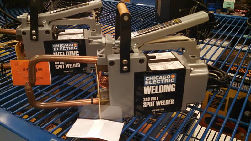
According to their supposed amp draw the 120v unit is only capable of delivering 1.6kVA vs the supposed 3.8kVA of the 240 volt unit. That is a pretty big difference and they cost the same so why would anyone go with the smaller unit? Well, if they don't have 240v available I guess. Even if I didn't have a 240v outlet in the house I would still probably get the 240v unit............Nah, I ain't going to tell unknown persons how to make it work. Either you know enough about electrical distribution and your house wiring for the solution to be obvious or you don't need to know because you might get into trouble.
That is a horrible tease right? Stop thinking about it cause I didn't do it anyway. I have a 30amp 240volt circuit in the laundry room. It is unfortunately the older 3 prong NEMA 10-30 configuration so I can't safely plug in anything that requires a neutral wire but none of my loads currently need that anyway and the spot welder as it comes from the store doesn't either (more on that later).
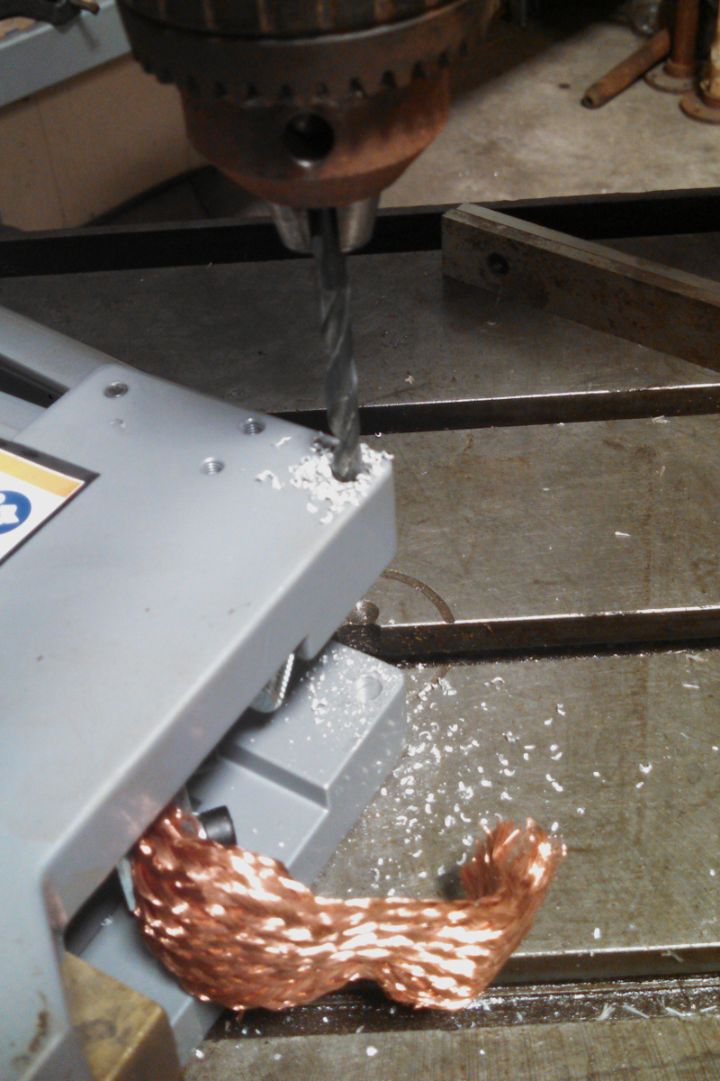
So I have a welder in hand now but what I haven't mentioned yet is that it isn't usable in the straight from the store condition. First of all, the pivot point for the upper bar is utterly sloppy garbage and without even turning the unit on (worked fine for me this time but bad idea in general for stuff bought at Harbor Freight) I drilled the offending pivot out for a larger screw with no slop.
The other big problem for me is the copper tongs. They only have a 6" reach but for the boxes I want to make a minimum 10" reach is required. The Harbor Freight unit is largely compatible with tongs made for the genuine Miller version but the cost of 12" tongs is +$100 and more importantly I wasn't sure the additional voltage drop across another 12 inches of 5/8" copper rod would be low enough to leave me with a useable capacity.
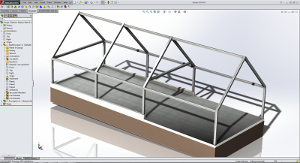
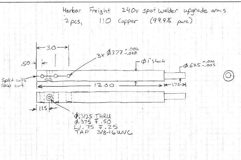
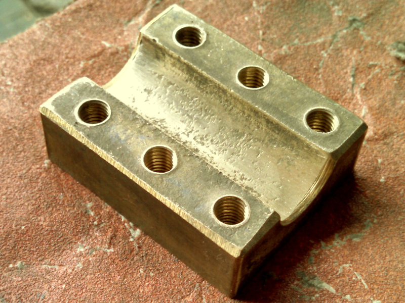
So what do I do? I go out and spend ~$130 on 3ft of 1" diameter C110 copper bar and some 3/8" bar from 6061dude on ebay (a good source for small quantities of aluminum etc...). The basic idea is to make what I see Dan Gelbart did on his spot welder. Here is a drawing of the two main bars.
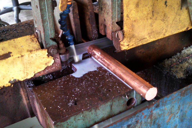
Throw the 1" bar on the bandsaw and cut off my two pieces about 13.8in long. My 3ft bar leaves an 8inch drop to use for something else.
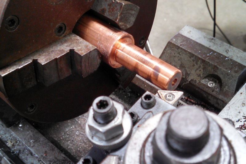
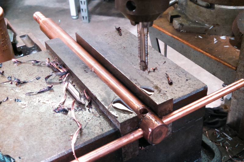
Then I faced both ends of each bar, and turned down a section on ones side to .625". Notice the color variation you can see in the area I just turned. I am using a high sulfur cutting oil and with the heat generated by turning it discolors the freshly cut material almost instantly.
I referenced my DRO from the edge of the vise and drilled the three .375" holes in a line
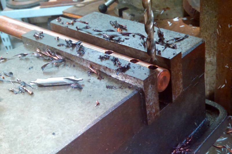
Then I stuck a rod through the first hole and used it to eyeball a 90 degree rotation so I could drill the second hole. I also used it as a stop to hit up against the vise edge which I had already zeroed to. This time I drilled through with a 5/16", followed by just past half with a 3/8" and then I power tapped 3/8-16.
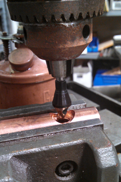
I wanted the screw heads recessed so I applied a coutnerbore using a 3/4" endmill and then cleaned up the hole edge with a countersink.

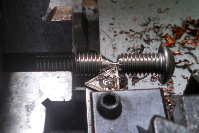
The button head cap screws that were available at my local store the day I went over there were too long so I trimmed them down on the lathe while I was in the shop. Notice that I am chucking straight on the threads but I don't care because they are the end I am cutting off.
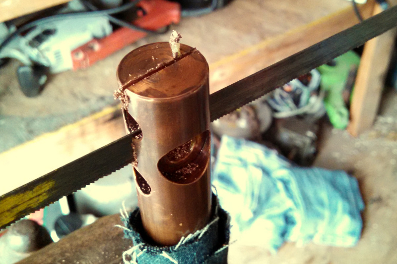
A few days later when I had some time again I split the bars by hand with a hacksaw and relatively coarse bimetal blade.
Before I put the new bars in I cleaned up some parts that had a rough as cast surface so they would provide as little resistance as possible.
I used one of the rods I will make electrodes out of to align the bars while I installed them in the welder and tightened everything up.
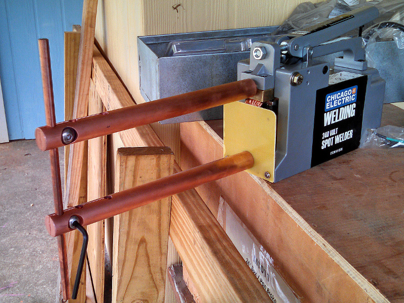
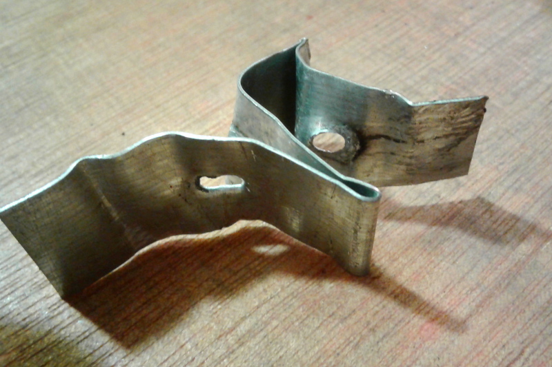
This whole time I was waiting for some twist-lock plugs to come in so I could hook the welder up to my large extension cable and the dryer outlet. They finally came in and I was able to make a few test welds. Here is a tear test of one of the welds that I will need to make in my bin project. It is 3 sheets of galvanized 26 gauge steel. Works perfectly and both side tore out a chunk of the base material instead of breaking the weld.
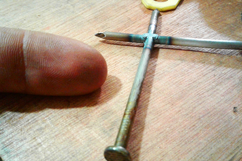
I am also interested in welding wires together. Did a pretty good job of some small nails.
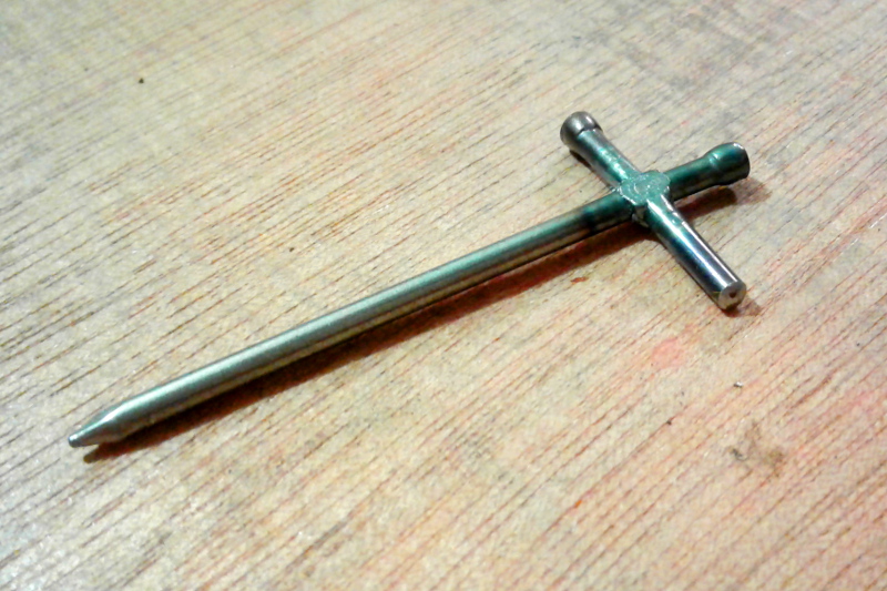
Then to see what the limit was I went with the largest nails I thought might work. At first they didn't work because of the sinker coating but eventually I was able to do the same thing to some larger ones. This is at the very edge of the units capability and probably took 6 or 7 seconds to do.
I also want to implement a weld timer so I can get consistent results. I thought about making my own timing circuit using either a variable resistor and capacitor circuit to turn a relay on/off but the size of relay required and the fact that I am running off of 240Vac instead made me decide it might be more work than required. I also thought about counting cycles or something with an MSP430 since I have a few of those lying around but I'm not really good at electronics or experienced with micro-controllers so that looked like it would turn into a larger rabbit trail than I wanted to get into. I eventually decided to just go old-school and use a technology that I know already exists, the time delay relay.
There are different kinds of time delay relays and if I was willing to pay a few hundred dollars for a brand new unit I know that interval relays (turn on for an interval, then turn back off) which control the size of load I have exist. I don't want to spend more on a relay than the welder itself costs though so I hunted around on ebay to come up with some components that I thought would work. I knew roughly how things were going to operate but didn't sketch up a circuit until I had found suitable parts.
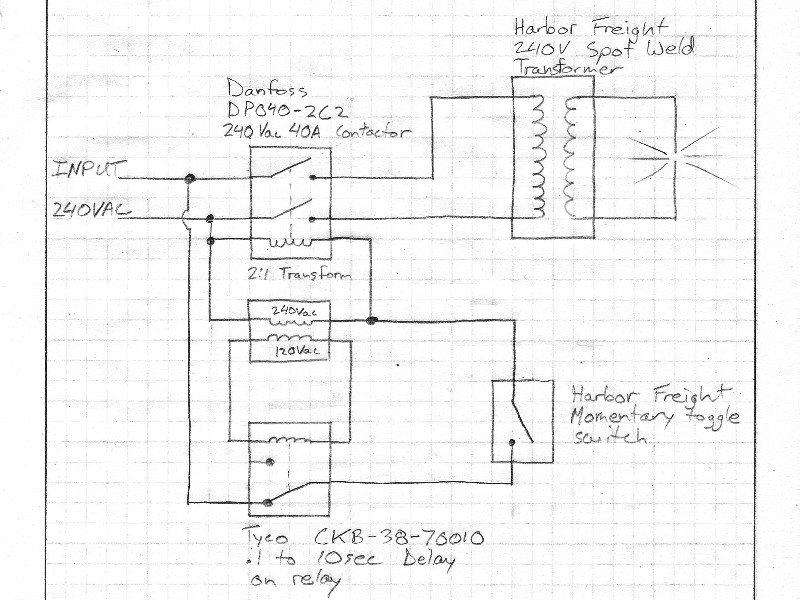
Now don't go make that circuit. I have determined that it won't work. When the switch is closed the contactor will energize (starting the weld) and the time delay relay will start counting. When the relay finishes counting it will go open circuit turning off the contactor and also removing power from itself. With no power to keep the relay open it will immediately switch closed again thereby re-energizing the contactor and starting the relay count down again. It will keep doing this until the switch is released and turns off the contactor and relay.
Those components can make a working circuit though.
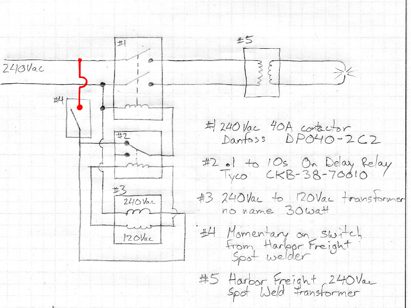
In this version the relay doesn't cut its own power supply so once it has counted down and turned the contactor off it stays latched until the trigger switch turns off and resets the relay.
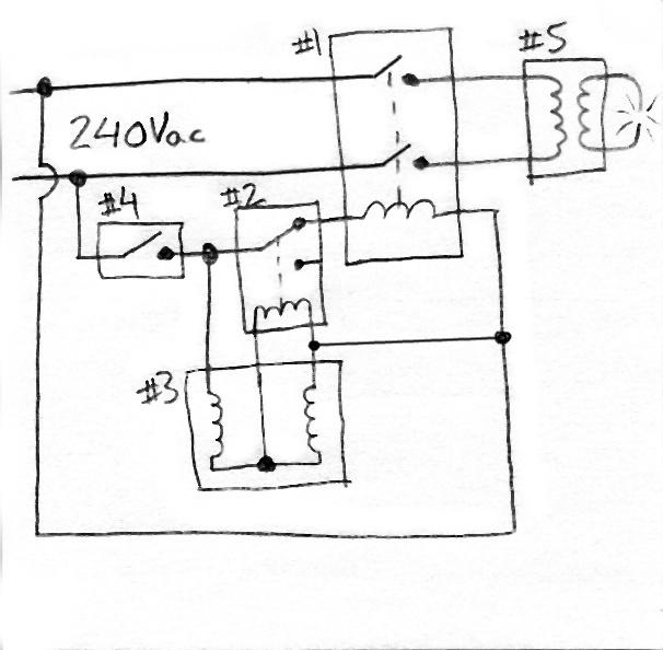
That isn't exactly the circuit I'm going to make though. When I tore open the little 2:1 transformer I had ordered I found out it wasn't a 2:1 isolation transformer but actually a a center tapped autotransformer. Not really important for what I am doing but a slightly different schematic, this time just sketched on a post it note.
Now, I'm not sure when I'll actually get around to implementing the timer. I have all the parts on hand but it isn't strictly necessary to use the welder and because of the relatively low power this one has weld times are longer than I expected so timing by gut feel isn't as unreasonable as I was anticipating. I guess I'll update whenever I do it.