

Ball Toy
August, 2017
While watching a youtube video we saw a cool toy with 1,000s of ball bearings sandwiched in-between two panes of plastic. It was pretty cool and Elizabeth said she really wanted one. Well I looked around and found that it didn't exist anymore. It was made in 1966 by Francois Dallegret and called Atomix at the time.
I thought it was too cool to not have one so I decided to have a go and make one on the sly without Elizabeth knowing. I'll claim it is because she said she wanted one and thought it would be cool for the kids but lets be honest, I wanted to make it.
So just slap some acrylic together with balls inbetween, simple enough right? The hard part is finding a ball and a sandwich layer that works out right. Buying 1/8" balls and using a 1/8" spacer wouldn't let them roll around but an 1/8" spacer and 3/32" ball seemed too loose. Surely there is some combo of metric / english spacer and ball that works. The answer is yes, I found cheap 3mm stainless bearing balls (3mm=.118") which means a 1/8" sandwich spacer should be just right. There is a gotcha though, nominal 1/8" doesn't mean exactly .125", it means .125" plus/minus a tolerance. For most sheet goods in this size that tolerance is plus/minus .010" or more. If it was oversize that would be fine but if it was undersized then .125"-.010"= .115" which is smaller than the balls and obviously not workable. Luckily, my favorite MRO (maintenance, repair and operations) supply company, McMaster Carr, has 1/8" thick 6061 aluminum sheet with a .005 tolerance. So I ordered the cheap 3mm ball bearings off ebay and purchased some 5/16" thick acrylic sheet, 1/8" thick aluminum sheet and aluminum low profile binding screws + barrels from McMaster Carr.
As always McMaster delivered the goods promptly. In this case since I ordered with my home shop account it arrived 2 days later. Pretty good for ground shipping rates and traveling from Atlanta, Georgia to Bryan, Texas but nothing compared to the speed I get at work on the account I spend a lot of money with. I don't know how they do it but for less than standard ground shipping cost any order I make before 5pm (and occasionally up to 6:30pm) arrives the next day before 10am. That is 17 hours shipping from Atlanta to Bryan every time for less than the cost of standard ground shipping!
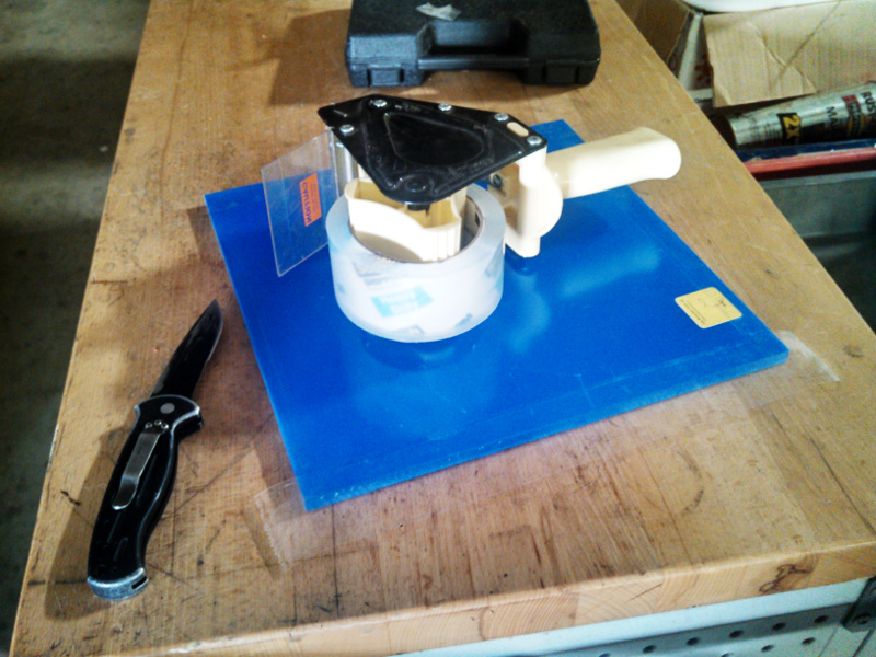
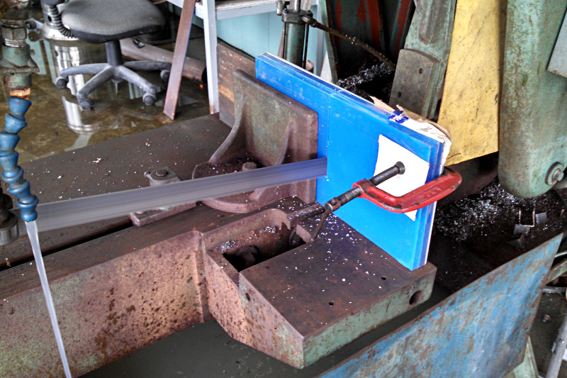
Ok, McMaster Carr is the best business ever and I love them. We are all tired of hearing me say that right? The sheet goods are in, time to start making something. I decided to tape up the edges of the plastic to help keep the protective film in place on the large plate while I cut it up into smaller tiles.
Then I threw the 12x12 plate in the bandsaw to cut it in half and after that took the two 12x6 halves and cut them to 6x6 along with the aluminum.
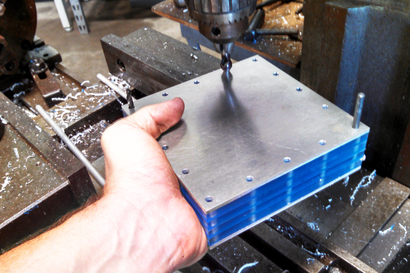
The saw cut is never perfect and I don't care about the exact dimensions so I stacked all my parts together and clamped them in the mill vise so I could trim them down to make nice square faces. Notice the clamp that I have on the stack, I put that on after I put the parts in the vise for two reasons. First it helped reduce the chattering that all those individual plates wanted to do supported that far away from the endmill. Second, it kept the stack together as I flipped it around to hit all four sides. I had to move it a few times to hit all the sides but re-positioning while the stack is constrained by the vise doesn't lose the relationship of the parts.
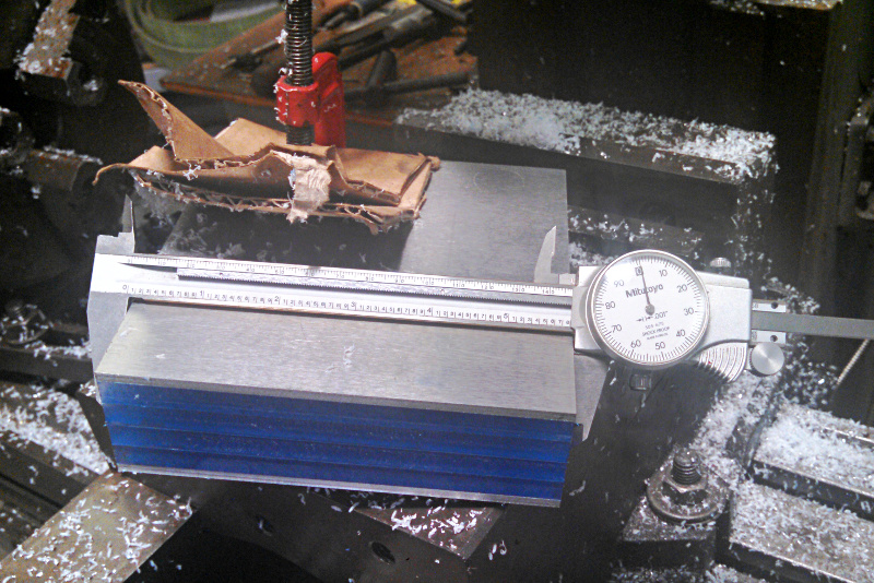
After trimming two adjacent edges with the same height set on the mill I measured what I had and decided on a final dimension. I measured about 5.885" so I decided to raise the table .085" and shoot for 5.800" finished dimension after trimming the two remaining edges I hadn't milled yet.
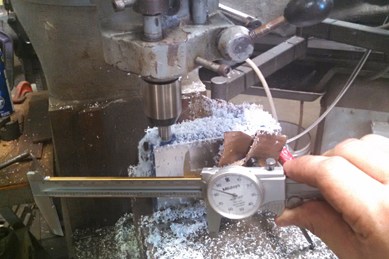
I hit 5.800" closer than I thought I would and certainly better than it needs to be. I'm not holding the caliper in place with the right tension so the reading is a little high the photo but according to them I was within about a half thou on both sides. Obviously that measurement is only accurate to a few thousandths but like I said, it is more than good enough for this application and I really have no need to check it with something more accurate, a tape measure would have been good enough.
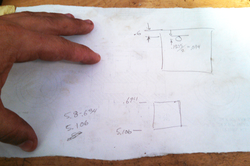
Like many of my other smaller projects I like kind of just winging things as I go. I didn't have a finished square dimension in mind before I started and certainly didn't have any hole placement figured out. This time though since I didn't have time to drill the holes the same day I cut the tiles out I actually sketched what I was going to do out on some engineering paper before I finished the project.
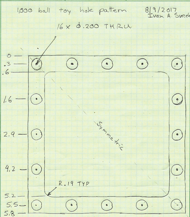
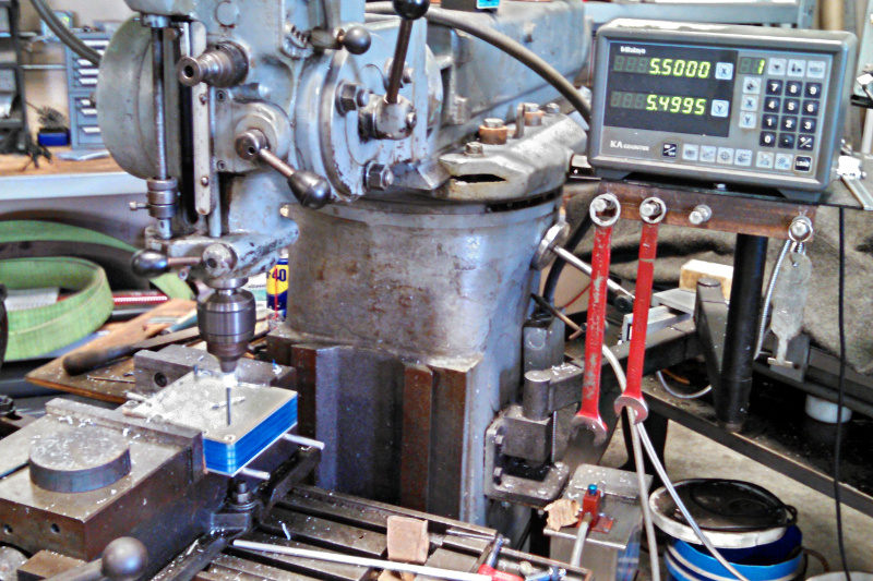
So when I had a chance to get back to it and add drill the holes I just needed to throw the part stack in the vise, indicate the DRO in and drill according to the numbers I now had on my nice drawing. It is as simple as that but I did make a mistake the first time I put them in the vise.
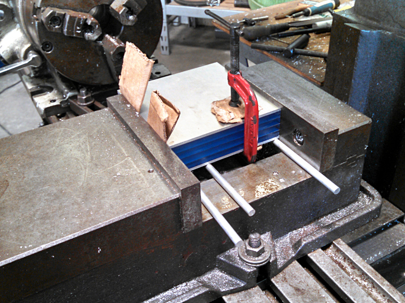
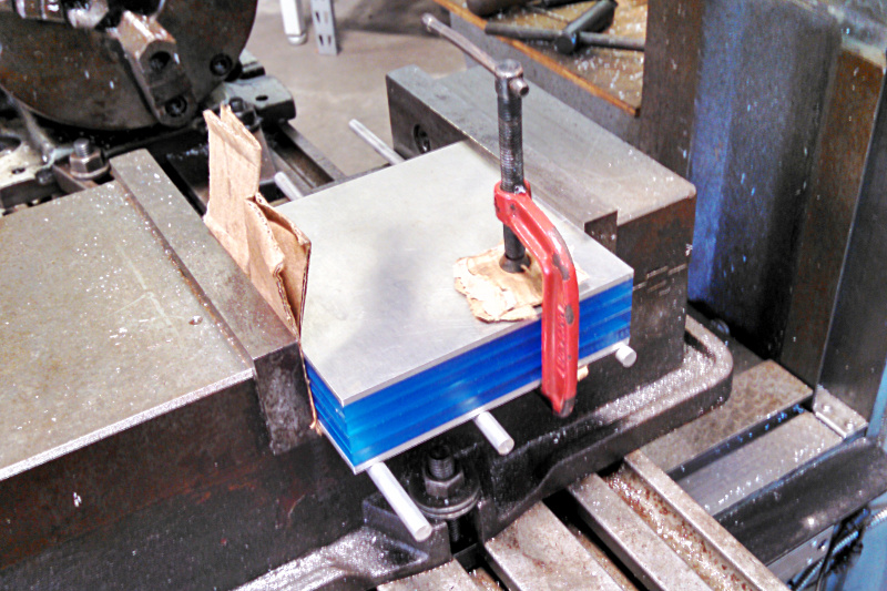
The aluminum rods to space it off the bottom of the vise are great and the bits of cardboard on the movable jaw side will take up the slight differences between plates but I can't get the clamp that holds the stack together out! So take two, the same same aluminum spacers and cardboard shims but this time I can take the clampp off and actually do the drilling.
Because this project is purely aesthetic and all of the holes will be match drilled at once finding my edges isn't a critical step. I just stuck the #7 drill in the chuck and ran the table up until the drill touched the fixed vise jaw and side of the stack then moved over .100" (~.201"/2)in X and Y to put the point over the corner of the parts and zeroed the DRO out. After that it is just drill according to the numbers on my sheet. If it was an application that really mattered and wasn't being match drilled then I would spot drill the hole pattern and then follow up with the actual drill but like I said, this being match drilled and purely aesthetic. A couple thousandths off won't make a difference. I did introduce the drill to the work slowly though to give it a chance to start each hole without too much walking before I gave it some pressure.
The interior parts in the stack are all backed up so there isn't a burr on the new holes but the exit side and to a smaller degree the entrance side both had a little raised material so I just barely knocked it off with a countersink. When I don't want a countersink, just a deburr, I run the tool real slow (maybe 400 rpm) and just kiss the part lightly by hand for a revolution or two.
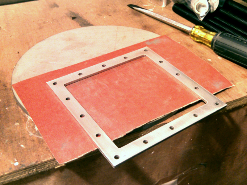
With the holes drilled there was only one more machining step left, cutting out the interior of the aluminum parts. I had a 3/16" endmill already loaded in one of my endmill holders so I decided to deviate from my nice pretty drawing and go with it instead of a 3/8" endmill. Regardless, before I cut anything I needed to determine what my table position should be to achieve the desired final dimensions. So I did a quick calculation on the back of a scrap piece of paper.
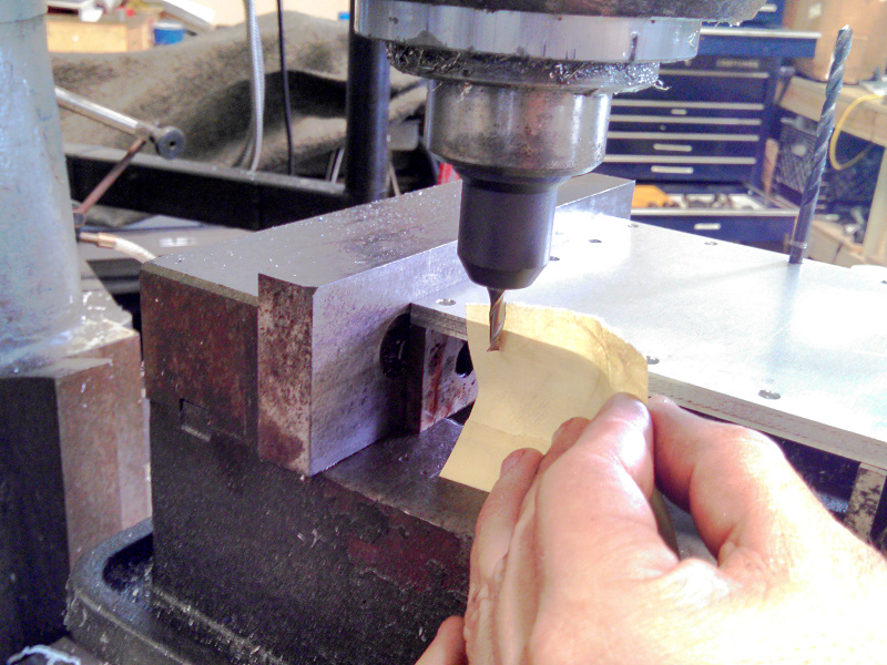
Now I put the aluminum parts back in the vise just like they were before (minus the plastic parts and supported by taller parallels instead of aluminum rod stock) so my DRO still had the fixed vice jaw side zeroed in close enough for this job. I had lost registration of the other side though so I touched off on it by using a piece of paper between the endmill and the parts to feel when they were touching. When the paper starts to drag while you wiggle it the tool is a paper thickness away from the part (in this case .005").
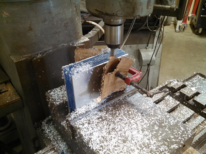
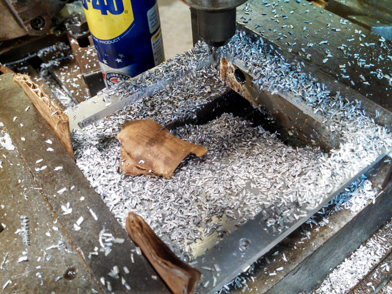
With the DRO zeroed again and my limits calculated I set about milling the interior. I didn't want to waste the material or spend the time to turn it all to chips so I dropped the endmill in .010" to the inside of my final cut then walked around the whole part and dropped out a rectangular slug from the middle. While cutting the last side I wedged some cardboard bits into the gaps and pulled the center away from the cutter while I completed the cut. After the middle piece dropped out I moved out the .010" I left for finishing and walked around the inside of the part to cut to final size. I did this with a climb cut (cutting in the direction which makes the tool try to drag the work into itself as opposed to pushing it away, a bad idea on worn out tools unless you are taking very small cuts) to make a nice finish.
To make sure everything sits flush during final assembly and keep from cutting myself before then I deburred all the edges of the aluminum parts with a noga tool.
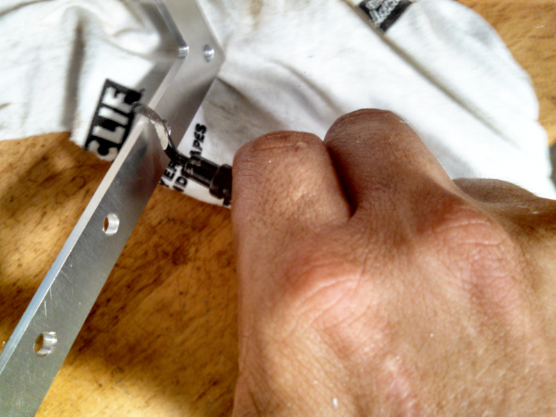
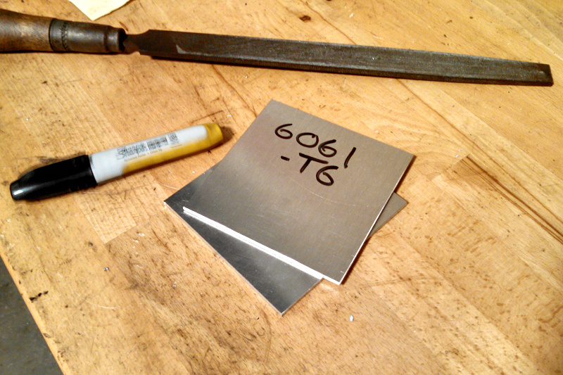
If your going to keep the scrap parts for another project and not dispose of them immediately then it is important to deburr those as well so you don't cut yourself when your rummaging around later(nope, I've never done that). I also like to mark the material so I know what I am dealing with. Makes it a lot easier in the future instead of trying to figure out if that sheet is 5052-O or 6061-T6 and you need to make a part with bends in it.
There is the result, machining is complete and the parts are ready for assembly.
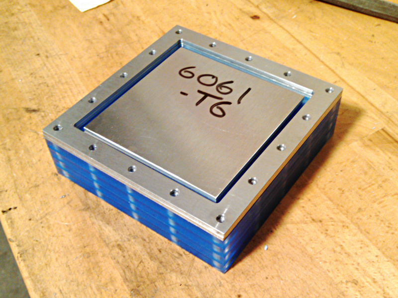
The balls still haven't come in yet so I can't do the final assembly and post-assembly finishing touches but I wanted to see what things would look like and test fit the two units with the binding barrels. The verdict, I think it looks good enough but should have drilled less holes. It is too busy and I think it will be excessive once the balls are in there and the protective plastic is removed. Oh well, it is what it is and I am certainly not unhappy enough to make them again!
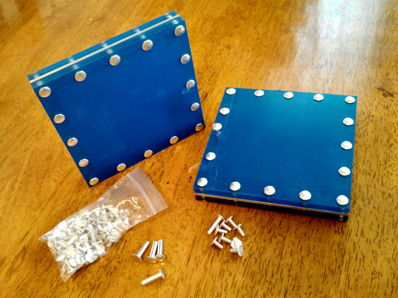
Now those balls just need to come in!
Obviously they eventually did but maddeningly only one of the two sets of 1,000 was actually in the package so I'll have to wait another 2-3weeks for finishing the 2nd toy. Anyway, back to the most exciting moment, putting it together. Before that though I needed to pretty up the aluminum spacer. I used some 220grit on a flat surface (9"dia x 1/4" thick stainless disc for the valve table) and sanded in a straight line to remove all the scratches and mill printing from both sides and make a straight grained brushed look.
When that was done I wiped the aluminum and both acrylic pieces down to remove any dust then removed the blue protective film from one of the acrylic parts. I put in a few binding barrels and placed the aluminum sandwich on then poured the ball bearings in.
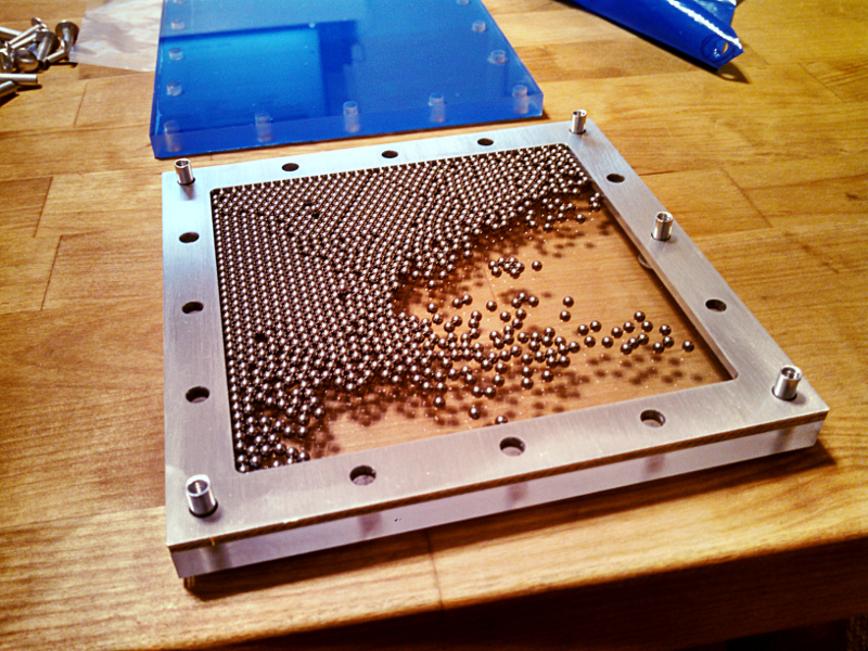
Now all I needed to do was remove the blue plastic from the other acrylic part and place it on top. That didn't go so well and I started loosing balls, Elizabeth grabbed a bowl for me and we shooed them all into the bowl then I tried again. The second time worked better and I got the top plate on without issue and installed a few screws. At this point the danger was over and I started putting in all the barrels and screws. The slots on these are really shallow, long and excessively wide so even my biggest flat head screw driver really wasn't big enough.
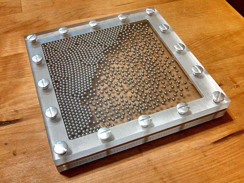
Important little side note on the screws: a little detail that really makes a difference if your project allows it is lining up all the screw slots or making them point some uniform direction. In this case I chose to line them up on the edges then split the difference in the corners.
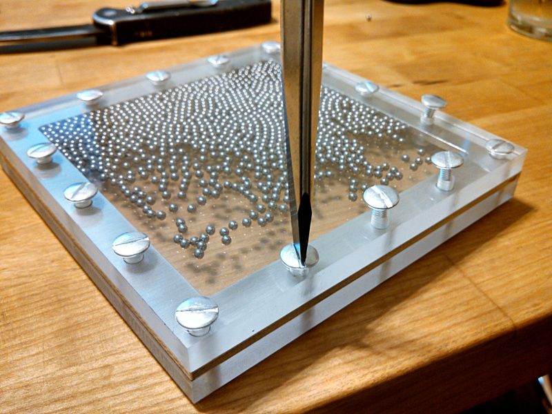
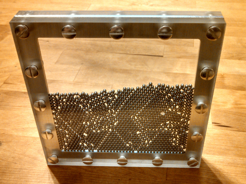
If you look back at the picture you will also notice something that isn't apparent at first. The balls are all spread out pretty evenly in the areas they aren't closely packed. Something about the plastic and metal balls makes them behave much more interestingly than just predictably rolling around as gravity pulls them. A static charge or other force causes the loose balls to flow around and repel each other, not something I was expecting and unfortunately not something that can be demonstrated in a picture. Fortunately embedding a youtube video is pretty easy!
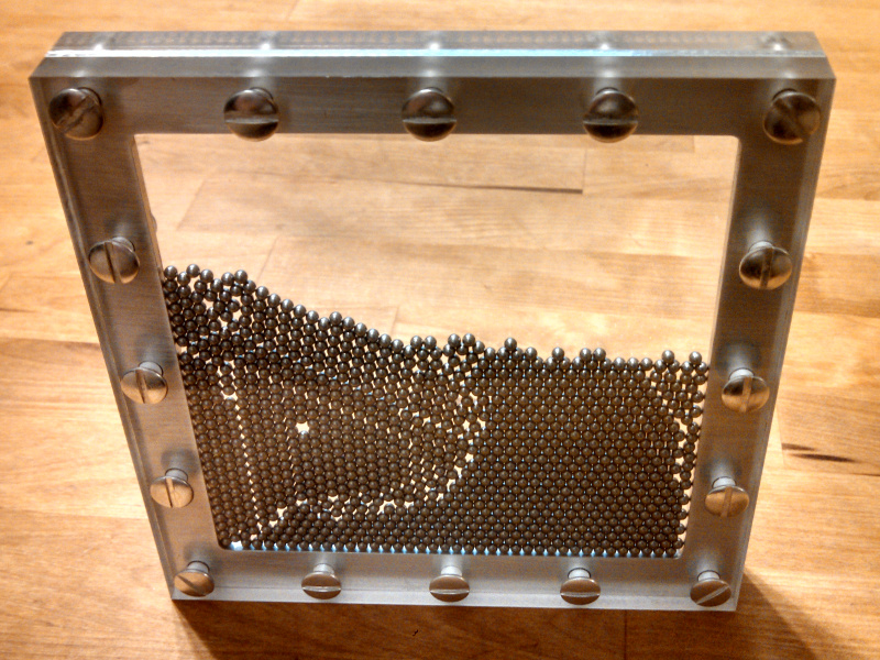
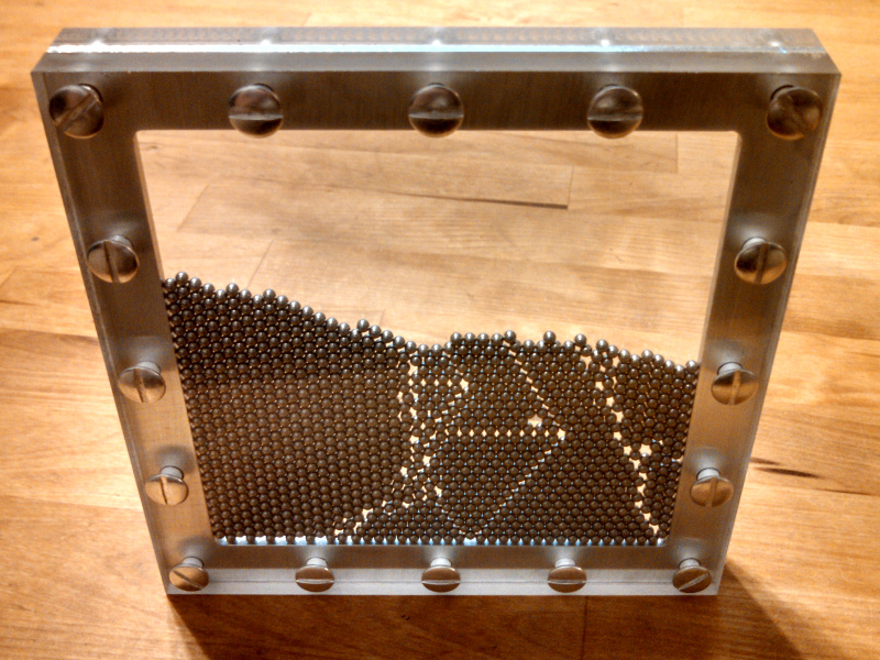
Now the effect I was intending to produce is clash of crystal structures. Due to much playing by myself and Elizabeth we have determined that (unintentionally) it is impossible for the balls to all stack nicely with a perfect structure. The dimensions are just wrong and they can't sit right so every time you turn the toy over it creates a different pattern of balls with cracks and vacancies and sometimes seemingly random segments. Here are a few pictures.
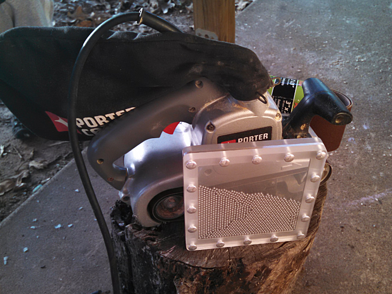
Now the corners and edges are still sharp as well as having an as cut finish. To take care of that I sanded down the assembled toy to make all the layers match perfectly as well as round the corners.
Then I tried flame polishing the edges after I finished up with the sander. I forgot to snap a picture (also, don't really have free hands when trying to do it) so there isn't anything to look at but it didn't go so well. Nothing is ruined but I wasn't able to get the clear look I was going for. I'll have to do some experimenting then try it again on the actual parts once I get it figured out.
Update, Rev 2
September, 2022
I did eventually get flame polishing figured out though I failed to write about it. The trick is to have the edges completely sanded down to 220 grit, give it a buff with 00 steel wool and then be skilled with the flame.
That skill was what was missing primarily with my first attempts. The key is to have a nice hot flame, watch the reflection of another light source on the acrylic and move fast! The reflection of the surface is muc more sensitive to watch than trying to look through the acrylic to judge if it is polished yet. The time from a fully melted, polished surface to over melted, starting to bubble/burn is a fraction of a second.
Anyway, I finished those first ones and liked them quite a bit so I decided that I would make another batch. This time around I decided it was a good excuse to purchase a chinese 6040 CNC router and make a little bigger batch in a reasonable time. So, I purchased materials and got the router. Then I spent a bunch of time getting LinuxCNC setup the way I wanted, brushing up on gcode, getting a CNC workflow set up and fixing a number of little stupid design issues with the CNC. Then other projects crept in and I didn't get back around to the ball toys until 2022.
Since one of the points of a CNC machine is running repeat parts over and over with as little human time as possible I needed a fixture that would hold the parts in a way that would be quick to use and require as few manual changes as possible. I thought of a few things and then decided that the best thing (if i could make it work) would be a vacuum fixture.
The concept is simple, make a plate with some holes in it and hook up a pump to remove the air so atmospheric pressure pushes the part against the table and clamps it in place for machining.
This doesn't work for all parts but I thought it would be a perfect fit for this situation. My machine doesn't have the rigidity to impose large cutting forces and these parts were thin, flat and a reasonable size. A quick back of the envelope calculation gives and idea of that clamping force available:
Part Area * Vacuum = Clamp Force,
(Length * Width) * (Atmospheric Pressure - Achievable Vacuum) = Clamp Force
(5inch * 5inch) * (14psi - 1psi) = Clamp Force (pounds)
(25in^2)*(13lb/in^2) = 325lb